May 2 2pm-3pm#
How do we design the amplifier's accuracy, linearity and bandwidth?#

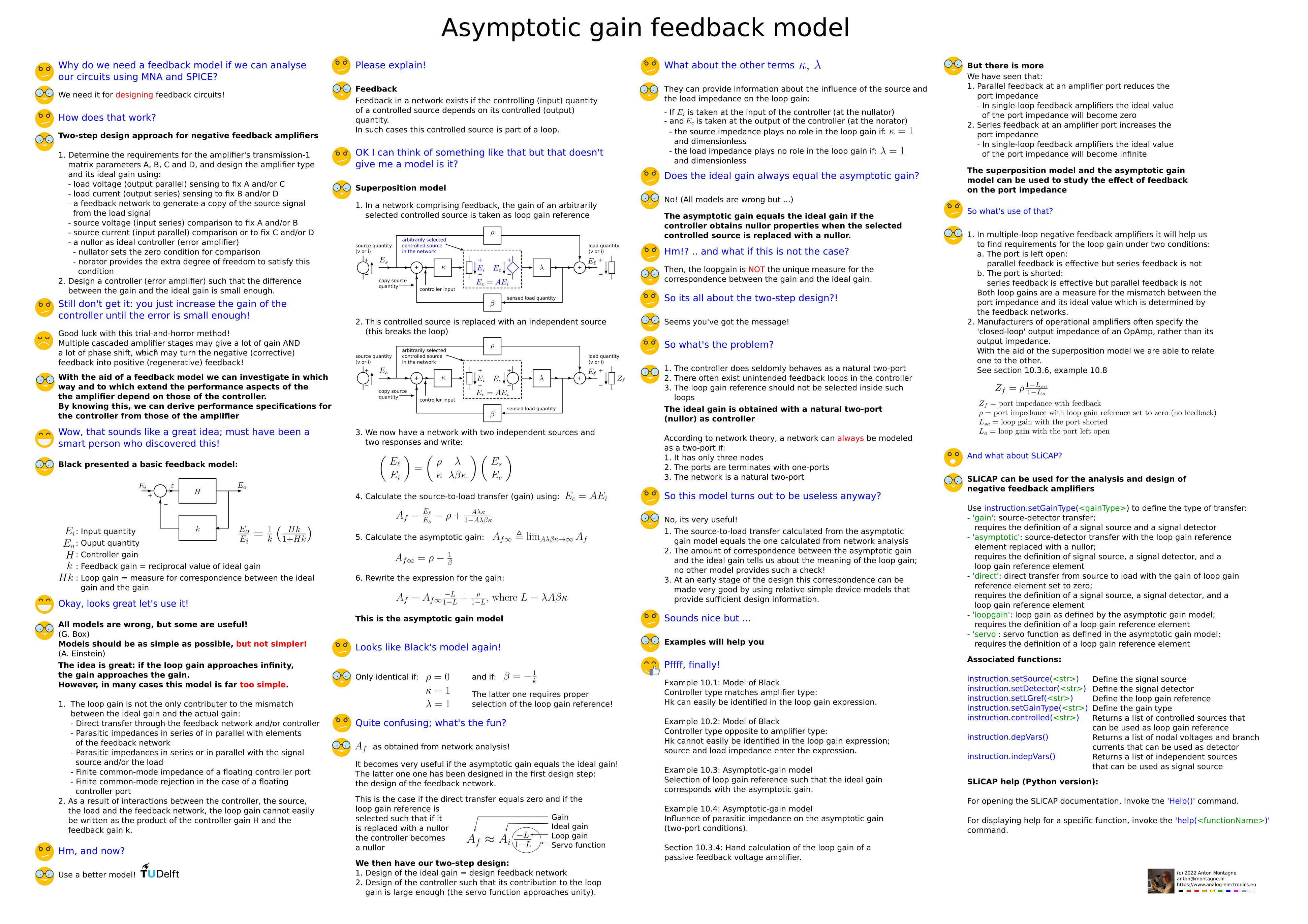
Feedback model#
The design of negative feedback amplifiers is performed in two steps:
Design of the amplifier feedback structure
Design of the controller(s)
The decomposition of the design into the design of a feedback network and the design of a controller requires that application-level error budgets also need to be decomposed. A part of the total error budget must be be assigned to the feedback network, and another part to the controller.
A meaningfuil error bugdet decomposition can only be made if we know how errors in different system parts propagate and are observed at application level. For the design of feedback amplifiers we need a feedback model that supports such a two-step design approach. Hence, it must provide a description for the transfer of the feedback amplifier that clearly separates two parts:
The transfer in the case of ideal controller (controllers are nullors), which only comprises feedback elements
The deviation from this fransfer resulting from imperfect behavior of the controller.
The asymptotic-gain feedback model provides such a description. It is summarized on the poster below and will be elucidated during this seminar.
Download this poster as pdf file"
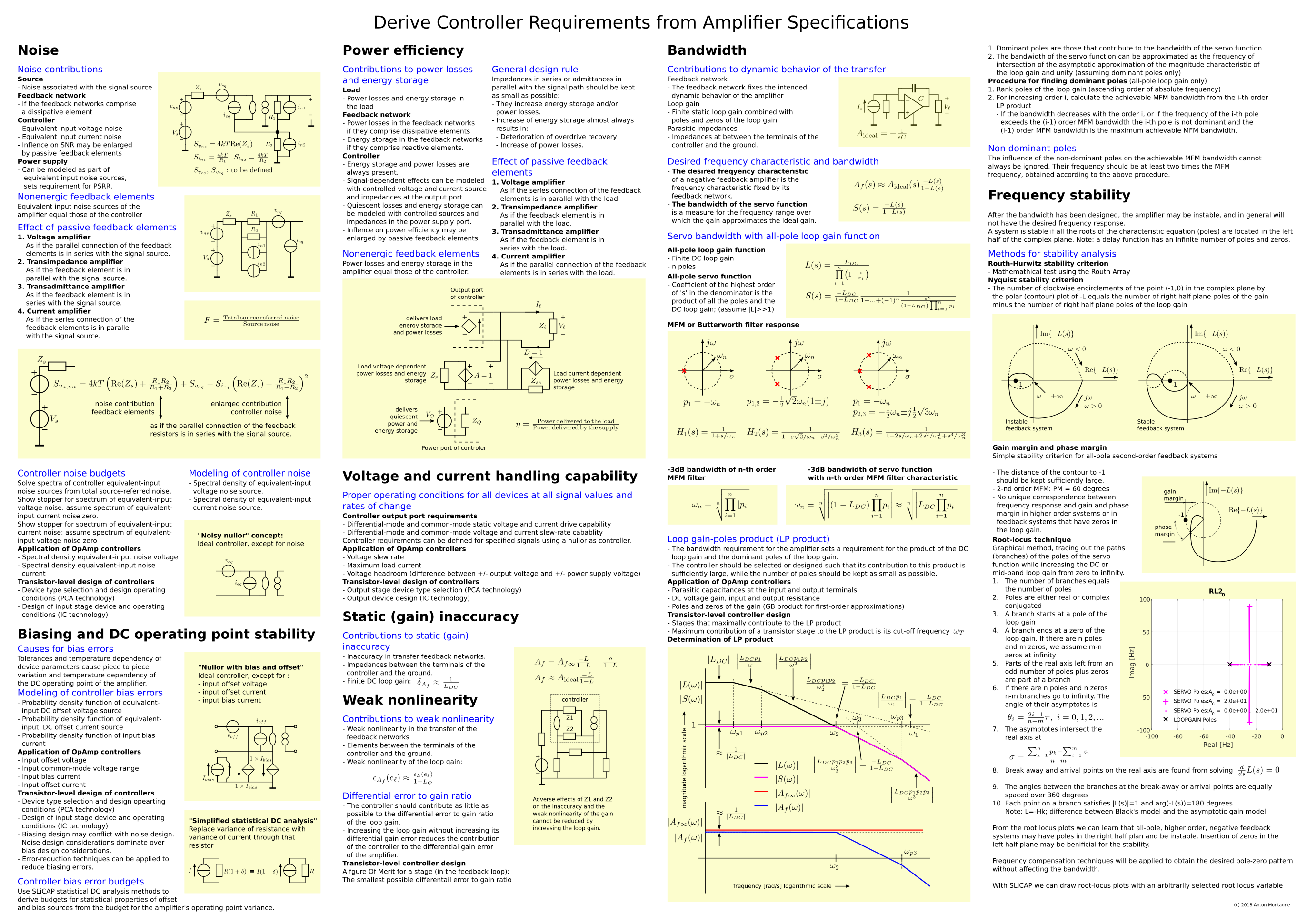
Relation between controller imperfections and amplifier imperfections#
The poster below summarizes the relation between imperfections of the controller (finite gain, finite bandwith, and nonlinearity) and the imperactions of the feedback amplifier. These relations will be explained during this seminar.
Download this poster as pdf file"