13-02-2025: Electronics 1#
Date: Thursday, February 13 2025
Location: Boole (36.HB.T0.610)
Time: 08:45 - 10:30

Question of the day
How do we design amplifiers from specifications?
Systems engineering and amplifier design#
These topics are for self-study they will be summarized during this lecture.
Basic Design Sequence
Structured design uses a design method that is equal at each hierarchical level of the product design.
Presentation
The presentation "Basic Design Sequence" shows the basic sequence of activities that converts a initial requirement for a physical object, at any hierarchical level, into a physical breakdown of sub-assemblies or parts.
Presentation in parts
Video
Information Processing: Definitions
In structured electronics design, we consider electronic products as information processing systems.
Presentation
The presentation "Information processing: definitions " gives the definitions of some basic terms used in information processing.
Presentation in parts
Information processing: definitions (parts)
Video
Information processing, definitions (4:19)
Study
Chapter 1.1, 1.2
Shannon: Channel Capacity
The expression for the channel capacity (Shannon 1948) shows us that there are three fundamental limits to the amount of information that can be processed by any real-world system:
noise addition
power limitation
speed limitation
Presentation
The presentation "Shannon: Channel Capacity" briefly elucidates this.
Presentation in parts
Shannon: Channel Capacity (parts)
Video
Fundamental physical limits to information processing (3:45)
Outline of Structured Electronic Design
Although not scientifically proven, we assume that the functional breakdown of information processing systems can be made with a limited number of basic electronic processing and reference functions.
By taking a limited number of functions as starting point for a design, rather than an almost infinite number of known circuits, is one of the keys of structured electronic design.
Functions concepts describe the idealized desired behavior of their real world implementations. The information handling capacity of these objects, however, is limited. This is a result of:
Noise addition
The physical limitation of the signal power
The physical limitation of the rate of change of a signal
Imperfect technological implementation of the desired functional behavior (physical operation mechanism)
The performance-to-cost ratio of an implementation can be improved through application of a limited number of error reduction techniques.
Orthogonalization of the design process can be obtained by proper sequencing of the design of different performance aspects.
Presentation
The presentation "Outline of Structured Electronic design" briefly elucidates the above.
Presentation in parts
Outline of Structured Electronic design (parts)
Video
Structured Electonic Design (12:27)
Study
Chapter 1
The amplification function
Amplification is one of the most important basic electronic information processing functions.
Presentation
The presentation Amplification gives a definition of the amplification function and elucidates the amplification mechanism.
Presentation in parts
Video
The amplification Function (3:35)
Study
Chapter 2.1
Amplifiers: performance measures, cost factors and figure of merit
During the design it is important to have some figure of merit for design solutions. Comparison of the figure of merit of different solutions is the basis for taking properly motivated design decisions.
Presentation
The presentation Amplifers, performance measures and cost factors gives a general performance measures and costs factors for amplifiers en proposes a figure of merit that can be used throughout the design process.
Presentation in parts
Amplifers, performance measures and cost factors
Video
Performance measures and cost factors (3:38)
Study
Chapter 2.1.3, 2.1.4, 2.1.5, 2.1.6
Electronics Design Sequence
Presentation
The presentation "Electronics Design Sequence" illustrates the use of basic functions and error reduction techniques in the basic design sequency.
Presentation in parts
Video
Case study#
Hearing loop system#
Hearing loop systems are used for broadcasting audio information to individuals with T-Coil equipped hearing aids. They are used in public areas such as theatres, churches, meeting and conference rooms, etc.
The architecture of a hearing loop system is shown in the Fig 1.

Fig. 1 Architecture of a hearing loop system: A loop antenna converts the electrical audio signal into magnetic flux. A receive coil in the hearing aid converts this magnetic flux into a voltage. An amplifier in the hearing aid amplifies this voltage to drive the loudspeaker in the hearing aid.#
The send and receive antennas will be provided. Behavioral models need to be based on measurement data, acquired during the demonstrations. Test and measurement equipment for characterization of the antennas is available in the Tellegen hal.
Target specification#
Maximum audio input level: 1V peak
Maximum audio output level with the receive coil placed in the center of the transmit coil: 0.25V peak
-3dB small-signal bandwidth: 300Hz ... 15 kHz
Full-power bandwidth: 300Hz ... 5kHz
Input impedance transmitter: > 10kOhm, over the frequency range of interest
Load impedance receiver: > 2kOhm, over the frequency range of interest
Receiver output noise (no input signal, frequency range 60Hz ... 15 kHz) < 100uV RMS
Power supply voltage up to +/- 15V
Power dissipation as low as possible
Tasks#
Groups of four to six participants will design, build and test a hearing loop system. Two or three participants design and build the transmit coil driver, while the other two or three design and build the receive coil amplifier. All group members participate in the selection of the system architecture (amplifier types) and in the the definition and the execution of the test plan.
The design comprises the following steps:
Derive the specifications from the application description and group them in
Performance requirements
Interface requirements
cost factors
environmental conditions
Design a lumped element network model of the transmit-receive antenna system
Set-up selection criteria for the electrical quantity driving the transmit coil and for the electrical quantity to represent the information from the receive coil
Design the system architecture, model the transfer, and derive specifications for the amplifiers:
type and gain
noise requirements
signal levels and drive capability requirements
frequency response
Design a test plan
Design the transmit coil driver amplifier
Design the receive coil amplifier
Present your project on a poster
Build the system
Execute the test plan
Discuss the results with each other and with the instructors
Links#
Data sheet 100mH receive coil: RL622-104K-RC
Demonstrations#
Characterization of the hearing loop transmit and receive coil
Impedance of the transmit coil
The inductance of the transmit coil is 314 uH. Its resistance is 8.1 Ohm and the self-resonance frequency is 0.86MHz.
Specifications of the receive coil can be found on its data sheet
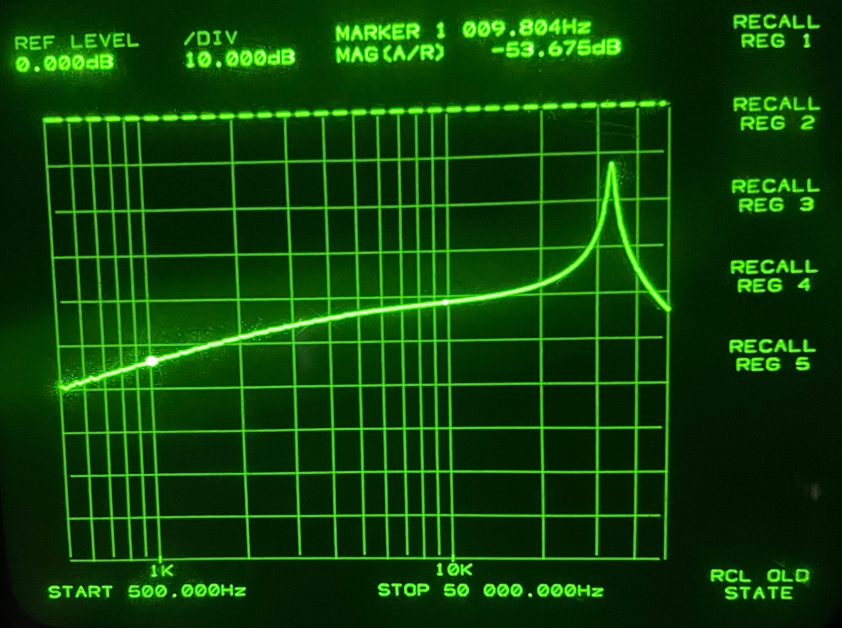
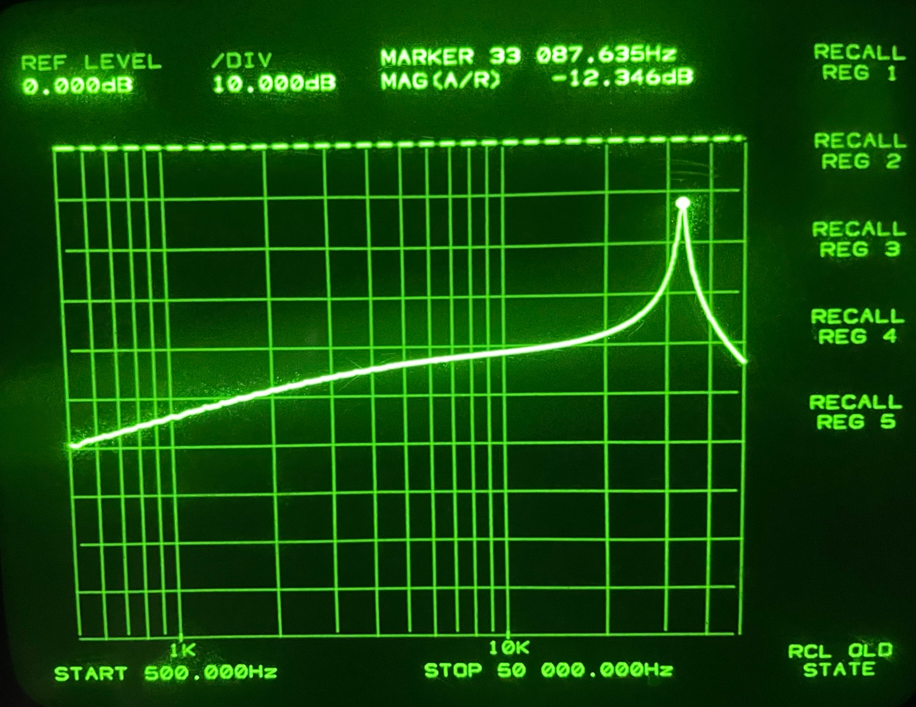
Transfer of the loop antenna system
The figure below shows the voltage transfer of the antenna system measured with an HP3577A. At 1 kHz the magnitude of the transfer is -53.7dB.
The figure below shows the voltage transfer of the antenna system measured with an HP3577A. The resonance frequency is 33.1kHz.
Discussion#
A network model that describes the above transfer with all known details.
Teaser for the next lecture: Let SLiCAP do the analysis!
Downloads#
Group exercises and homework#
Create and/or join design teams of preferably six students per group.
Discuss the completeness of the hearing-loop system specifications within your group and if necessary add specifications to be defined later.
Create a network model of the hearing loop antenna system that enables you to determine coupling factor from the measurements. The model should be as simple as possible!
Install SLiCAP and kicad (version 8) and run and study the tutorial
myFirstRCnetwork.pyor the jupyter notebookmyFirstRCnetwork.ipynb. You will find these files after installation of SLiCAP in the folder:~/SLiCAP/examples/myFirstRCnetwork/. You can also download the archive myFirstRCnetwork.zipSee SLiCAP HTML help for more information.